Tramming the bed of Kobra 2 Max
This is an update to our previous Thoughts on Kobra 2 Max. We would like to share our experience with tramming the bed of the Kobra 2 Max.
As we mentioned previously, the 7x7 49-point auto-bed-leveling seems not sufficient enough for such large bed. The nozzle always gets too close to the bed where the screws are.
The auto-leveling sensor on this machine is basically a small metal detector. It will only sense the spring steel under the PEI coating, which might not be accurate if the PEI coating is not the same thickness. We also suspect the screw holes on the magnet sheet affecting the value of the sensor, as metal detector relies on magnetic field, and we still get high spots around the screws after tramming the bed.
We spend sometime on the following to get a good first layer.
Disclaimer
We are sharing our experience solely for informational purposes. We do not encourage users to disassemble the printer or adjust configuration files that are not meant to be accessible by default. We do not accept responsibility or liability for any damage caused to the printer as a result of following modifications.
Tramming the bed
We don't think this will be necessary after we find a way to manually modify the bed mesh. But it might help if you want everything perfect.
There are 8 metal spacers under the heat-bed which are not height-adjustable. We replaced 7 of them with silicone spacers (bought from Aliexpress, and we will have them in-stock in our next shipment), that allowed us to adjust the height of the bed at corners.
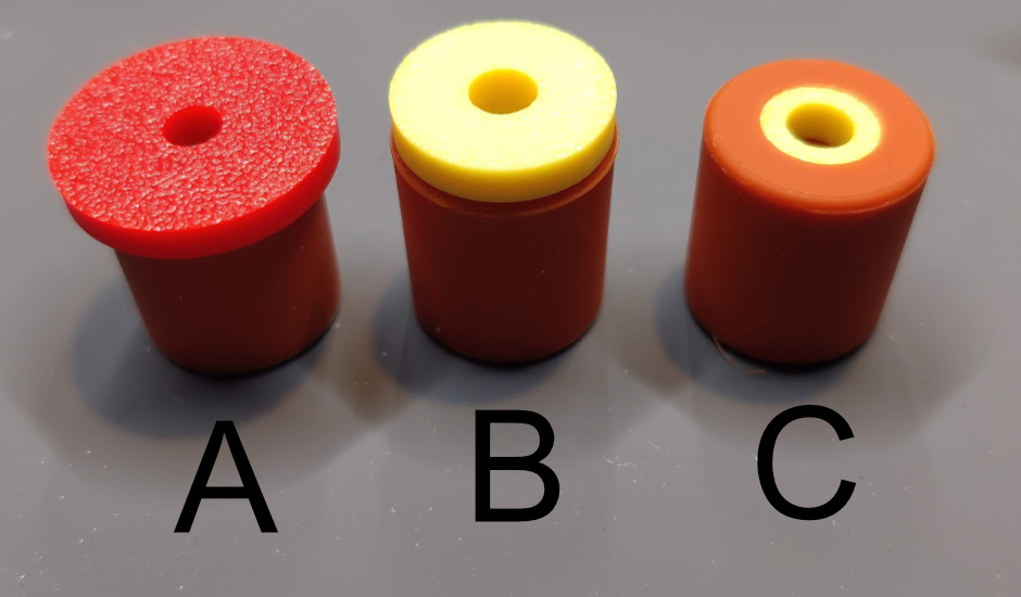
The silicone spacer we used is 18mm tall and 16mm diameter. Total 7 of them. Combine with 3 different printed (PLA will be fine) shim and installed as follow:
![]()
- "O" is the original metal spacer. We left this one there as the original height reference, all other 7 silicone spacers will try to match to the same height as this one.
- Shim A, 4 of them. (credit: https://www.printables.com/model/753702).
- Shim B, 1 of them. (credit: https://www.printables.com/model/739358).
- Shim C, 2 of them. (credit: https://www.printables.com/model/739358).
-
The spacers with shim, 4 x A, 1 x B, 2 x C, all installed with printed parts facing down (away from heat bed).
- Get a digital dial indicator, print the dial indicator mount found here https://www.printables.com/model/730729, we used the "Tight Fit Snap On Cap X Gantry (Replacement Cap Version v1).stl" to make sure the dial indicator is fixed tight on the X even during move.
- Set the point of "O" as 0, then use the screw to adjust "B" to 0, then one of the "C", then the rest clockwise. There won't be perfect all 0, it will be fine to have around 0.02 differences. Here is a Youtube video showing doing it https://www.youtube.com/watch?v=eV9AGm6lLHg, although it is not clockwise but a little random.
- Remember to re-run auto bed leveling and adjust the z-offset after changes.
Adjust bed mesh manually
Please note: This is only for experienced users, modifying printer.cfg will void your warranty.
Anycubic does not open source their Klipper based KobraOS (it is heavily modified Klipper, since they need to get it working with the AMS clone in Kobra 3) and block external connections to the OS. There is no way natively to modify printer.cfg but someone found a way to download/upload the printer.cfg through USB drive. Full story and credits go here https://klipper.discourse.group/t/printer-cfg-for-anycubic-kobra-2-plus-pro-max/.
The gcodes can be downloaded here. There are 2 gcodes in the zip, using them by "print" the gcode file on the printer:
- 1_download_cfg.gcode: It will download "printer_max.cfg" and "unmodifiable.cfg" to the root of USB drive.
- 2_upload_cfg.gcode: It will upload "printer.cfg"(remember to remove the "_max" from filename) and "unmodifiable.cfg" on the root of USB drive back to the printer. Again, doing this will void your warranty. There are lots of different keys/values from original Klipper's printer.cfg, do not change them!
To get the bed mesh and values need to be updated, we did the following steps:
- Run the auto bed leveling and adjust the z-offset. The bed mesh values won't be saved if auto bed leveling is not run before.
- Read through https://www.printables.com/model/671915, print the "Brim Test Max.3mf" to correct z-offset in the center, then print "430x430 without skirt" to see where needs to be adjusted.
- Print the "1_download_cfg.gcode" to download the printer_max.cfg, make a backup of this file!!!!!.
- Open printer_max.cfg with text editor(Notepad will be fine, but will be better with a full functional text editor like Visual Studio Code). Find the line near the end of the file, starts with "points : " following 49 decimal numbers, copy the whole line.
- Paste the whole line to the page we made to simplify the process: Kobra 2 Bed Mesh Adjustment.
- After adjustment, paste updated values to replace the original line that start with "points : ", do not change any other lines.
- Rename the file to "printer.cfg" and place onto the root of USB drive, print the "2_upload_cfg.gcode" to update the printer.
- Restart the printer, print the "430x430 without skirt" test pattern again.
- Repeat 2 to 7 if necessary. Do not run auto bed leveling as it will restore original values.
- It will need to adjust z-offset through the printer's printing menu when bed temperature is different, e.g., increase (move nozzle up) the z-offset when printing PETG as hotter bed brings the nozzle closer.
Start G-Code Update
We updated our start gcodes, now it only heat up the nozzle before extrusion.
; Start G-Codes
G90                                 ; use absolute coordinates
M83                                 ; extruder relative mode
M140 S[first_layer_bed_temperature] ; set bed temp
M190 S[first_layer_bed_temperature] ; wait for bed temp
G28                                 ; move X/Y/Z to min endstops
G1 Z20                              ; nozzle to 20mm
G92 E0                              ; zero the extruded length
G1 X3 Y3 F6000                      ; move to 3 x 3
G1 Z2                               ; nozzle to 2mm
M104 S[first_layer_temperature]     ; set extruder temp
M109 S[first_layer_temperature]     ; wait for extruder temp
G1 Z0.28                            ; nozzle to 0.28mm
G1 E6 F500                          ; extrude 6mm
G1 X180 E25 F500                    ; extrude 25mm of filament in a 18cm line
G1 Z2                               ; nozzle to 2mm
G1 E-0.4 F3000                      ; retract 0.4mm
G92 E0                              ; zero the extruded length again
G1 X181 F4000                       ; quickly wipe away from the filament line
M117
End gcodes also here, same as previous post.
; End G-Codes
{if max_layer_z < max_print_height}G1 Z{z_offset+min(max_layer_z+2, max_print_height)} F600 ; Move print head up{endif}
G1 X5 Y{print_bed_max[1]*0.85} F{travel_speed*60} ; present print
{if max_layer_z < max_print_height-10}G1 Z{z_offset+min(max_layer_z+70, max_print_height-10)} F600 ; Move print head further up{endif}
{if max_layer_z < max_print_height*0.6}G1 Z{max_print_height*0.6} F600 ; Move print head further up{endif}

G1 E-1 F3000                 ; retract 1mm
M140 S0                      ; turn off heatbed
M104 S0                      ; turn off temperature
M107                         ; turn off fan
M84
*The bed photo is stolen from https://www.printables.com/model/671915. All credits goes to the author.